Thursday, March 23, 2023

HomeKit Compatible Bluetooth Relay for $7

After installing an electric gate opener for my driveway, I decided that I did not want to have to always carry around the remote control. Setting up a keypad or RFID reader was an option, but it would require a lot of digging, setting a post, running wires, and it would not be cheap. What I really wanted was a way to open the gate (using the gate controller's external button switch connections) from my iPhone. The gate is far enough away from my house that a WiFi connected relay was not an option. Also, I did not want to have to install and use some proprietary app just to push the button. That narrowed down the requirements to a HomeKit compatible Bluetooth relay. Unfortunately, I could not find any general relays for Homekit that used Bluetooth (Apple's MFi is not very DIY friendly).

Enter the SYLVANIA SMART+ Bluetooth Outlet, compatible with Alexa, Apple HomeKit, and Google Assistant, currently available for a bargain $6.99 on Amazon. It makes a lot of sense to use in locations where you don't have WiFi, or just can't use the WiFi you have access to (like in an office). Of course, this is not a general purpose relay, and I don't need a switched 120V outlet. But, I expected that it was just a relay inside and I hoped it could be easily disconnected from the mains electricity and instead connected to switch low voltage.

When the outlet arrived, I followed the directions, briefly installed the Sylvania App (which did not require me to create an account!), updated the firmware, and had it running in HomeKit within a few minutes. I then deleted the Sylvania App and still had complete control of the outlet from my iPhone Control Center. Now for the fun part!

The outlet's PVC cover seemed quite well bonded together so I pulled out the hacksaw to cut it open around the perimeter of the enclosure near the back.

With the board liberated from its enclosure, it was quite easy to see how the relay (data sheet) was connected to switch the hot side, connecting the plug to the outlet when activated. I desoldered the two plug receptacles for the hot and neutral sides of the outlet. This also separated the Common terminal of the relay from the outlet. Then, i needed to separate the Normally-Open side of the relay from the plug. I used the edge of a small file to cut through the solder and copper on both sides of the board until I was through to beige PCB material all the way across the trace. There are a lot of tiny vias in this trace, so it is important to double-check it with a magnifying glass and verify that there is infinite resistance between the relay terminal and the hot plug prong.

Next I soldered a wire to the relay Common terminal, and another to Normally-Open terminal. I connected these wires to a 5v power source with a current-limiting resistor and an LED. I carefully plugged this contraption back into an outlet, and... the iPhone HomeKit button worked perfectly to control the low voltage and LED!

Since I was pretty careful opening everything up, it will not be too hard to glue the enclosure back together with some PVC cement so that it can be used safely. In the meantime, I routed the wires out of the hole for the outlet's ground, added some spade terminals, and taped the cover back on.

I was really happy with how simple and cheap this project was and that it worked perfectly the first time. The modified Sylvania HOME+ Bluetooth outlet will make a great HomeKit relay for projects not in WiFi range. Here is the final install in my gate opener controller box, connected to the external button switch terminals:

Tuesday, March 3, 2020

DSC Alarm Garage Door Opener

Connecting your garage door opener to a DSC PowerSeries alarm system is pretty simple and gives you the benefit of being able to close the door from your alarm system panel. If you have an EnvisaLink module installed in your alarm system, you can also control it from your phone anywhere in the world. Unfortunately, most modern garage door controllers are more than just a contact switch. For instance my LiftMaster Security+ 2.0 opener uses a serial data connection over the low power door switch lines. Still it is not too hard. If you have a "smart" garage door opener, here is how to do it for about $20:

Parts Needed

  • Another Garage Door Opener Switch that matches your existing wired switch (mine was less than $20 on eBay)
  • 12V relay, high level trigger ($1-$2 on eBay)
You kind of have to sort through eBay to find ones that are cheap and do the trick. you don't need opto-isolation. The ones in the picture below work well.

Instructions

  1. Take the case off the garage door switch so you just have the PCB.
  2. Solder 2 pieces of wire, each about 4" long to the contact switch legs. You may need to experiment to find which are only connected to each other when the button is pressed.
  3. Connect the other end of each wire to the screw-down block on the relay module. One goes on the common "COM", and one goes on the normally-open "N/O" terminal, but it doesn't matter which is which.
  4. Use double-stick foam tape to attach the relay to the garage door opener switch.
  5. Run 2 wires from your alarm system control box PGM terminal to the garage door opener. I ran a cat5 cable, which left me with enough wires to add a magnetic switch on the garage door, a heat sensor on the garage ceiling (smoke detectors may give false alarms due to exhaust fumes), an auxiliary buzzer so that I can hear when the keypad sounder is beeping, and the connection to the garage door opener.
  6. Solder or use a molex connector to connect the wires from the alarm system to the relay input header, one on IN and VCC, and one on GND, making sure to preserve the polarity from the alarm box.
  7. Unplug your garage door opener and connect two 8" long wires from the screw terminals on the opener to the garage door opener terminals. Make sure to connect to the wired switch terminals and not the sensor terminals, and make sure to preserve the polarity listed on the switch. I had to add new machine screws and nuts since the original ones went into the switch's plastic case.
  8. Then, match the switch to the opener by pressing the contact switch a few times.
  9. Once it is working use double-stick tape to attach it to the opener, making sure not to short out anything on the metal opener cover.


Friday, October 25, 2019

SMART Response XE - Intro and opening it up

Intro

The SMART Response interactive response system is an assessment tool that enhances learning. It facilitates summative and formative assessment by enabling you to pose a question before, during or after a lesson to find out whether students are on track. You can use the feedback to help shape the rest of your lesson.

But really, it is a cool form factor LCD + QWERTY keyboard, and a hackable micro controller (ATmega128RFA).

Opening it up

  1. Find the joint on the edge and use a spludger or guitar pick to pop off the grey bezel. Work your way around to free the clips.
  2. Starting at the power button, force the spludger in between the lower and top case. This applies pressure to separate the top and bottom case.
  3. Use a small screwdriver to push in the plastic retainers at the larger openings. There are 2 on each edge, closest to the corners.
  4. The case should start to pop apart as you apply pressure inside each opening and pry downward.
  5. Work your way around, each of the 8 clip openings.

Your adventure begins!

Friday, February 23, 2018

ESP32 first timer

I have been messing around with a Wemos Lolin32 ESP32 module that I recently bought on ebay for a few bucks. I'm not totally sure what I am going to do with it yet, but it looks awesome for easy IoT home automation. I have had some early successes after some difficulty so I wanted to share my methods and results on Mac OS x.

Unfortunately, the Lolin32 module I bought was not pre-loaded with the AT command interpreter that seems to be standard. I ended up with 2 different ESP32 boards from separate ebay sellers which seem to be pre-loaded with only a simple test program. The manufacturer of both of them seems to be "TTGO". Anyway, it is definitely something to be aware of if you don't want to be doing a lot of programming and flashing just to get the AT command interpreter for an internet modem. Fortunately, Espressif Systems, the company that manufactures the ESP32, has done an excellent job of providing development tools and open sourced software for the chip. It is nice to see great macOS support from this company. Most Chinese manufacturers seem to focus on Windows only and maybe Linux.

Things you need to install for building and testing the AT command terminal:

If you have the CJMCU FT232H (or FTDI UM232H(-B), or Adafruit FT232H breakout), like I am using on my Apple II Disk emulator, connect it to the ESP32 module like this (we don't really need CTS/RTS yet, though):

ESP32 signalESP32 GPIO# (Lolin32 labels)FT232H (CJMCU labels)
RX16AD0
TX17AD1
RTS14AD2
CTS15AD3

Follow the instructions for flashing the AT command firmware. Basically: git clone --recursive https://github.com/espressif/esp32-at.git $ cd esp32-at $ make menuconfig In the menu that appears, set:

  • Serial flasher config
    • Default serial port to:
    • /dev/cu.SLAB_USBtoUART
$ make $ make erase_flash $ make flash

Along the way, you may get errors about some python modules that are missing. To resolve these, just install the listed package...
$ sudo pip install pyyaml xlrd
... and re-run the command with the error.

The first time I ran everything, I was getting brown-out errors in the debug console. I changed USB cables and did not have any further power problems.

The biggest issue I had was actually communicating with the AT command terminal using the "screen" command in macOS. No matter what I typed, the ESP32 would echo, but not respond. The basic problem had to do with line endings. Using miniterm.py rather than screen solved the problem, but a adding bindkey "\015" stuff "\015\012" to the ~/.screenrc file also worked. I couldn't get the stty screen commands like onlret or onlcr to work correctly.

Or, you can configure the ESP32 to use <CR> line ending, like it should have:

$ make menuconfig
  • Component config
    • AT
      • enable: AT command terminator support.
      • set :AT command terminator. to:
      • 0x0D

Once everything is connected and built, you can connect to the device with:
$ screen /dev/cu.usbserial 115200,cs8,-parenb,-cstopb
or:
$ miniterm.py /dev/cu.usbserial 115200
Of course, you may need to add a numeric extension after "cu.usbserial", depending in what is in your /dev/ folder.

Quick ESP32 AT Trouble-Shooting Guide
IssueLikely CauseSolution
Garbage characters received from ESP32Incorrect Baud rateset terminal baud rate to 115200, or the same rate specified in make menuconfig.
Typed characters do not appear in terminalIncorrect RX/TX connectionsverify that wires to ESP32 UART1 are not crossed and have continuity
Typed characters appear in terminal, but no response from ESP32Incorrect line endings from terminalUse miniterm.py, or modify ESP32 settings with make menuconfig, or modify screen bindkey settings in ~/.screenrc
Typed characters appear in terminal, but still no response from ESP32ESP32 is hung from previous incorrect line endingsReset ESP32

So, after all of that I am to the standard default set-up that most people get already installed.

Tuesday, December 5, 2017

How about some Home Automation?

So, I totally ran out of steam on my RetroChallenge 2017/10 project. Tons of IRL stuff took over all of my attention. One of those things was buying a new house. That is sure to shift my attention away from RetroComputing for a while, so I thought I would blog my adventure with home automation. Starting from the beginning...

Home Automation Goals

  • secure
  • relatively inexpensive
  • high WAF (easy to use and stable)
  • iPhone Home app (HomeKit) compatible
  • good integration with various technologies
  • stay out of the cloud
  • Bonus: integration with DSC alarm and Alexa
  • Bonus: run on a Mac
I don't mind a complicated set-up, as long is everything is stable enough that my wife doesn't get annoyed at things not working. In general, home automation subjects seem well-documented on the internet, and I can hopefully program around any total road blocks I have. Since I have an older Amazon Dot around here, and I have experience programming a DSC alarm system on my old house, support for those is an added bonus.

Initial Research

While Apple's HomeKit looks very slick, it, of course, uses a Apple's own protocol, and the devices seem fairly expensive. I would like to use some cheaper alternatives, if possible. Insteon seems like a very solid choice, but their products are not cheap either. And the Insteon Hub Pro HomeKit-Enabled is not getting good reviews. I'll leave the home automation protocol comparisons to others, and I may wait a bit to choose a final solution for my in-wall dimmers and such.
With my hesitancy to commit to a standard other than Apple's Hope app, and the need to have good integration with other technologies, I will need a very flexible solution. openHAB seems to fit the bill nicely. It has support for Alexa, bindings to interact with HomeKit, DSC alarm systems, and pretty much anything else you could want.

433Mhz Wireless

Since Insteon and Homekit accessories are fairly expensive, and I haven't committed to a standard yet, I was eager to see products that supported many of the cheap wireless outlets and accessories. These 433Mhz devices aren't secure, but I will only be using them for testing and low priority items.
Hook is a great example of a product that integrates Alexa and these cheap outlets. But, Hook uses the cloud and I don't see much support for it under openHAB.
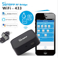
The Sonoff RF Bridge is a similar product which is VERY cheap on eBay. It looks great, except it also uses the cloud. What is cool about it is that you can flash it with new firmware to make it use MQTT and make it very openHAB compatible. But, I'm not sure I will have the patience for all of that. They are so cheap, I bought one anyway to try out.
RfLink Gateway is another nice piece of software, but again, too much flashing and hardware hacking for now.
Finally, I found the Broadlink RM Pro which is essentially a WiFi enabled IR/RF universal remote. It is basically an inexpensive Logitech Harmony Hub (which is also supported by openHAB, and would make a great alternative). It has some early openHAB support and will work with 433Mhz RF or infrared remotes. As a bonus, it already works with Alexa. They are also inexpensive. I just bought one on eBay, and I'm eager to try it out. Hopefully, I can contribute to this binding being fully featured and supported in openHAB.


Alarm System

My new house does not have an alarm system installed. I installed a DSC alarm system kit on my old house and found it to be very reliable. It was nice to see openHAB has good support for the DSC Ethernet module. I saw an excellent deal for a kit on eBay and just bought one. The kit is the "DSC KIT64219SE". It is basically a hybrid wired/wireless DSC alarm system from their PowerSeries. The price was way too good of a deal to pass up, even though escrow has not yet closed on the house! I will need to buy a lot more sensors, detectors and an ethernet interface to complete the install though.

Running total:

ProductDescriptioncostqtytot
DSC KIT64-219SEHybrid Security System163.531$163.53
Broadlink RM03 ProWiFi IR/RF universal remote33.811$33.81
Sonoff RF Bridge 433WiFi 433Mhz RF Bridge (needs re-flash)10.391$10.39
Grand Total$207.73


Friday, June 14, 2013

New Blog for Retro Computing

I moved my Apple II and Retro Challenge content here:
Apple Crapple

If you linked from Hackaday.com, the post you are looking for is here:
http://apple-crapple.blogspot.com/2013/01/karateka-and-schematic.html

If you are looking for my RetroChallenge 2013WW content, it is here:
Apple Crapple/RetroChallenge_2013WW

I will keep updating this site with Mac and LCD specific stuff.

Sunday, February 17, 2013

iMon_Helper Open Source

The iMon_Helper is now open source and is available at SourceForge.

Saturday, February 2, 2013

iMon Helper utility updated

iMon_Helper has been updated to provide (slow) remote control support without needing Growl. In addition, I compiled it to be a Universal Binary. View the included README file for details.

Download the latest version now!

I am hoping to get this project up on SourceForge to encourage further development.

Sunday, January 8, 2012

iMon Helper utility available

I just completed a new helper utility that will allow a standard LCDproc install to communicate with your iMon display. No more compiling special Mac OS X iMon drivers for LCDproc!

iMon_Helper is intended as a go-between to allow your Mac OS X installation of LCDProc to communicate with your iMon display. Because it is installed a separate binary, you will not need special Mac OS X specific compilations of LCDproc or the iMon driver to take advantage of the features of your iMon display. This will allow you to keep updated with the latest features of the iMon LCDproc driver.

Download the latest version now!

Unfortunately, I have not tested it on the newest Mac OS X or in 64 bit. Leave a comment if you have any problems.

Cox web hosting also recently ended their service, so the previous downloads I have posted are no longer available. I will try to get a version of GrowLCDproc up ASAP.

Tuesday, March 8, 2011

Receiving HID remote codes!

So I tried taking another look at getting remote codes from my iMon Soundgraph (0x0038) LCD. I am receiving the remote codes finally! I need to do some more work cleaning up the code and I think I can get something released!